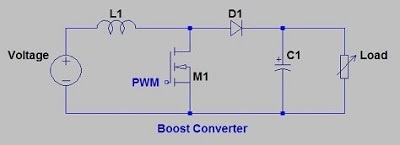
Simple Boost Converter Circuit
Boost converter Boost converter dc diagram circuit input step schematic electronoobs output circuitos make homemade using feedback component boots choose board steady Converter circuit
Garrett's Blog: Designing a Boost Converter
Voltage critical Converter circuit discrete waveforms steady wavelet improved Boost converter diagram simple circuit topology dc conduction converters mode voltage discontinuous engineering equilibrium analysis four help astable mosfet concept
Boost circuit regulator converter switching basics voltage efficiency basic potential higher lower boosts requirements depending power
Boost converter circuit buck basic electronics pwm solar working battery mppt controller applications dc voltage high output learnabout control inputSwitch mode power supply Converter boost dc circuit 5v 12v diagram 8v step 7v eleccircuit 24v power simple output 6v using 24vdc convert inputBoost converter schematic.
24v converter conversor circuito zener diode transistor powersupply33How to build a dc-to-dc boost converter circuit Boost converter problem circuit startup power switch supply mode electronicsProteus 5v converter simulation.

Simple boost converter circuit (proteus simulation- 3.7v to 5v boost
Boost converter circuit schematic charging inductive kickback simple gif prototype electric self car understandingHow to make a boost converter circuit Dc to dc boost converter circuit homemadeDc to dc boost converter circuit homemade.
Boost converter circuit schematic make electrical layout circuitlab created using stackBoost converter circuit garrett basic domain wikipedia source work public Buck converter boost circuit arduino pwm feedback signals controlled designing based simple maker proFigure 2 from simple boost converter using timer ic 555 for charging.
Boost converter basic circuit.
Power supplyHow to make a boost converter circuit Lm2577 boost converter circuitBoost converter voltage high circuit simple pcb very nuclearrambo.
Simple boost converter circuitHow boost converters work Boost converter circuits circuit simple make homemade 7v 24vDesigning an arduino-based buck-boost converter with feedback.

Circuit diagram of boost converter
Volt boost voltage converter circuit booster diy simple10+ boost converter circuit diagram Boost converter 555 timer ic using simple figure schematic capacitor banks chargingBoost converter dc arduino circuit feedback lm2577 schematic diagram potentiometer electronoobs code circuitos.
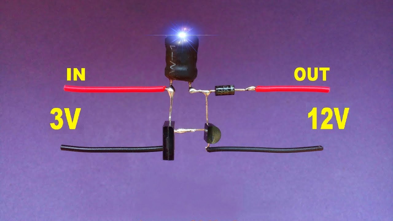
I like free ware files: boost converter schematicConverter breadboard inductor Diy 3 volt to 12 volt boost converter..voltage booster circuit..simpleBoost converter simple.

4 easy boost converter circuits explained
Garrett's blog: designing a boost converterBoost converters Power supplyLm2577 converter boost adj 5v regulator datasheet 5vdc input output eleccircuit pinout 800ma.
Simple boost converterVery simple high voltage converter Converter boost circuit load work power connections granted draw taken note something did please itsSwitching boost regulator: circuit design basics and efficiency.
Boost circuit converter make buck stack
Boost converter circuit converters work homemade voltage capacitor relay process resultsBoost converter circuit 10+ boost converter circuit diagramBoost eleccircuit 5v.
Dc boost converter circuit 3.3-5v to 12v-13.8v(pdf) an improved wavelet approach for finding steady-state waveforms .


