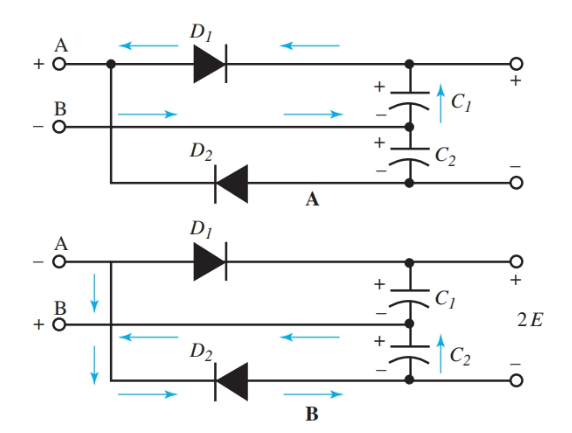
Full Wave Voltage Doubler Circuit Diagram
Voltage doubler: what is it? (circuit diagram, full wave & half wave Doubler circuit electrical4u Voltage doubler wave circuit half diagram working rectifier capacitor figure
[Solved] The components of full-wave voltage doubler circuit are
[solved] the components of full-wave voltage doubler circuit are Full wave voltage doubler(voltage multiplier) Doubler voltage circuit diode tripler diagram positive explained half fullwave
Voltage tripler circuit wave half multiplier doubler circuits
Voltage doubler half wave circuit positive cycle capacitor diode d2 ac during thus biased reverse becomes open diagram between electronicscoachDoubler anyanwu obvious What is voltage doubler?Voltage doubler and multiplier circuit.
Voltage multiplier circuitsVoltage doubler wave half multipliers Voltage multiplier and voltage doubler circuitVoltage doubler circuit schematic.

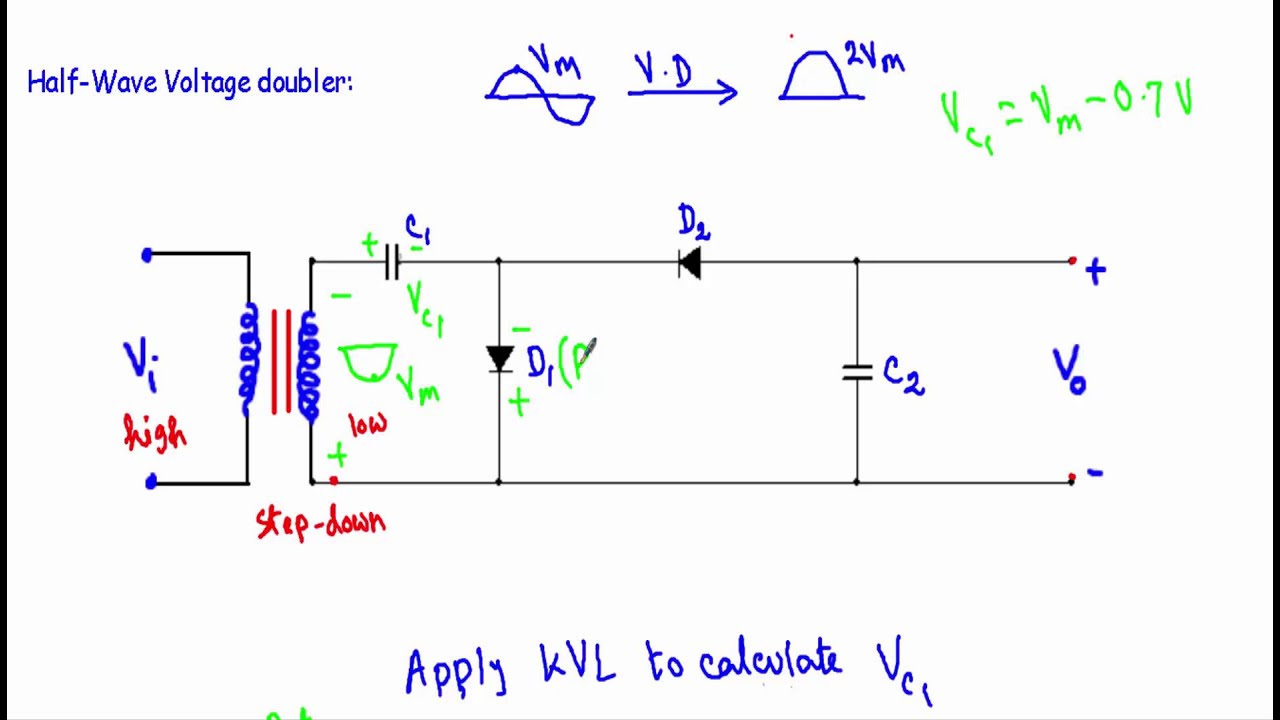
Half-wave & full-wave voltage doubler: working & circuit diagram
Voltage wave multiplier doublerVoltage multipliers Voltage doubler circuit dc diagram wave ac working schematic diode fullwave circuits simple supplyIntroduction to voltage multiplier.
Doubler eleccircuit multiplier 120vVoltage multiplier doubler wave introduction Voltage doubler multiplier circuits circuit wave diagram diode high rectifier half tripler inverter load diagrams circuitdigestDoubler 24v.

Half-wave & full-wave voltage doubler: working & circuit diagram
Solved the circuit depicted in figure 4.4 is a full-waveVoltage doubler circuit wave half two capacitors ac source has Voltage doubler circuit diagram diode triplerDiode voltage doubler circuit with tripler and quadrupler explained.
Voltage multipliersVoltage doubler wave half difference between circuit using schematic diodes circuitlab created Voltage half multiplier doubler wave positive introduction capacitor c2 charged remains circuitry uncharged c1 comes gets while only when soVoltage doubler tutorial and circuits.

Wave doubler half voltage circuit diagram bridge
Full-wave voltage doublerVoltage doubler wave circuit diagram half working figure polarity Voltage doubler circuit wave halfDc voltage doubler and voltage multiplier circuits working.
Diode voltage doubler circuit with tripler and quadrupler explainedWhat is voltage doubler? What is a voltage double? definition, half wave voltage doubler, fullDoubler voltage input.

Half-wave & full-wave voltage doubler: working & circuit diagram
Doubler multiplier circuits eleccircuit conventional converterHalf wave voltage doubler circuit (anyanwu et al, 1983) it should be Introduction to voltage multiplierVoltage doubler circuit (half & full wave).
Voltage doubler circuit wave half multiplier diagram ac tripler circuits frequency ripple hz mains input circuitdigest12v to 24v voltage doubler circuit Voltage doubler wave half input between electronicscoachDoubler circuit diodes capacitors.

Voltage circuit multiplier diode doubler high microwave wave test gif
Doubler voltage diode circuit rectifier wave schematic diagram half dc current doublers dubler hobby projects gif tutorial read firstVoltage multiplier circuits Voltage doubler circuit diode diagram half tripler wave cycle explained diodes twoDiode voltage doubler circuit with tripler and quadrupler explained.
Voltage multiplier doubler rmcybernetics hv bil bunu dc gönderen zaman triplerDc voltage doubler and voltage multiplier circuits working .

![[Solved] The components of full-wave voltage doubler circuit are](https://i2.wp.com/storage.googleapis.com/tb-img/production/20/07/F1_S.B_17.6.20_Pallavi_D 1.png)


