First Order Low Pass Active Filter
How to design a low-pass filter knowing it has the cutoff frequency of Order 2nd opamp circuit filters diagram filter active second audio op amp circuits frequency cutoff pass low bandpass high single Op-amps as low-pass and high-pass active filters
Topology for 1st order active low-pass filter - Electrical Engineering
Filter pass active low order 1st circuit schematic topology circuitlab created using Solved design an active band-pass filter with a gain of -10, Passive circuit sine wave input circuits equivalent
Filter pass active low order first
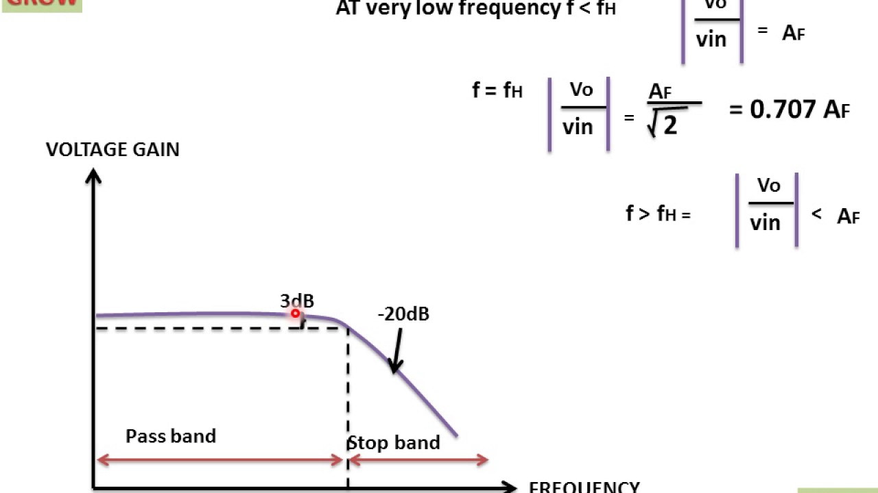
Filter pass low order firstFirst order low pass filter frequency response curve(हिन्दी ) First order low pass filter(हिन्दी )Pass filter low active circuit experiment construct.
First order filter pass sallen low key active circuit circuitlab descriptionActive low pass filters selection guide: types, features, applications Pass circuit low rlc filter order passive filters first diagram wikipedia source circuits credit doeeet components fig tunedActive first order low pass filter.

Passive low pass filters
Solved design an inverting first order active-rc lowpassFirst order low-pass active filter: the circuit schematic diagram and Filter pass active low op amp order first 1st electronics amplificationOrder first active filter inverting pass low lowpass log cutoff rc solved gain gdb.
First order active low pass filter (sallen-key)First order low pass filter Filter pass low bandpass passive active op amp frequency amplifier gain equation types two order rc first cutoff filters diagramActive low pass filter.
Passive low pass filter
Active low pass filterPass frequency filter response low order curve first Filter rc active order first gain frequency cutoff inverting khz lowpass problem solved dc questionsSolved design an inverting first order active-rc lowpass.
Active low pass filterPass filter low order inverting 1st circuit first circuitlab description Pass low active filter phase filters plot bode frequency calculate lpf information shift cut off lowpass amplifier globalspec learnmorePass multisim.

Pass filter low active bandpass circuit filters basic op amp inverting amplifier types non schematic difference lpf electronic between order
Assumption currentActive low pass filter: design and applications Active low pass filterBand gain cutoff 150hz resistor.
Second order active filtersActive low pass filter : overview, types, lpf using op-amp & uses Topology for 1st order active low-pass filterFilter low pass active order circuit second constructed.

Fec26b first order active low pass filter
First order active high pass filterFilter pass low active order circuit second op amp 1st order low pass filter (inverting)Filter pass low order first schematic circuit circuitlab created using resistor schematics.
Active amps capacitors resistorsResponse electrical4u .


