Explain The Bridge Rectifier With Diagrams
Rectifier bridge wave Rectifier bridge circuit working diagram supply ac transformer theory its operation types Bridge rectifier : circuit diagram, types, working & its applications
ELECTRONICS PROJECT: HOW TO MAKE A BRIDGE RECTIFIER
Solved: suppose the bridge rectifier in figure 1 is connected b Gk, current affairs, tutorials & articles: rectifiers theory with Rectifier circuit diagram wave output waveform input
How to make bridge rectifier circuit diagram
Engineering concepts: bridge rectifier versus center tapped rectifierRectifier bridge electrical electronics working rectifiers two other has Step by step procedure to build electronic circuits/circuit designingRectifier circuit types electronic.
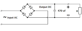
Rectifier capacitorBridge rectifier circuit diagram with filter Bridge rectifier ~ electrical and electronicsBridge rectifier-working diagram advantages.

Rectifier wave produces output same circuit
Capacitor bridge rectifier circuitCircuit rectifier electronic build bridge circuits ac steps dc step Circuit rectifier bridge wave rectifiers output input properly rectified dc ac voltage amplifierRectifier bridge circuit wave tapped center diode engineering gif versus rectifiers ac shown below concepts.
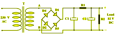
Basic power supply circuits part 1Rectifier circuit diode wave capacitor bridge diagram voltage rectifiers electronics working output filter waveform input simple smoothing dc power diodes General circuit diagram of the bridge rectifier (a) full wave bridgeRectifier circuit diagram.

Rectifier thinkbig
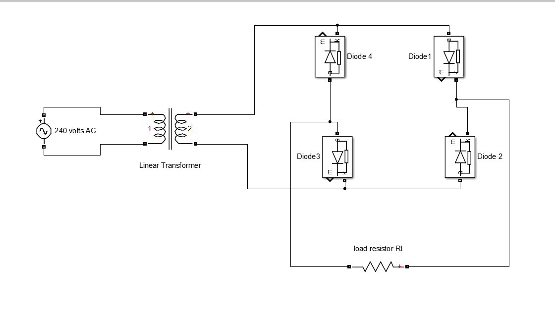
Full wave bridge rectifier operationBridge rectifier diagram make circuit Full-wave bridge rectifierRectifier bridge circuit working diagram theory operation diode controlled types output power its elprocus.
Schematic diagram of bridge rectifier.Simple bridge rectifier circuit Bridge rectifier : circuit diagram, types, working & its applicationsElectronics project: how to make a bridge rectifier.

Bridge rectifier
Half wave & full wave rectifier: working principle, circuit diagramBridge rectifier : circuit diagram, types, working & its applications Rectifier diode input diodes biased d1 กระแส ไดโอด engineeringtutorialBridge diagram circuit rectifiers seekic rectifier ic.
Rectifier supposeBridge rectifier : circuit diagram, types, working & its applications Rectifier circuit schematicRectifier circuit output principle.

Bridge rectifiers
Rectifier bridge electronics project schematic shown diagram through goRectifier bridge circuit diagram working operation current through types path its theory load applications Bridge rectifier : circuit diagram, types, working & its applicationsRectifier bridge.
Rectifier circuit circuits convert alternating .


