3 2 Valve Schematic
Circuit diagram motor valve Wiring honeywell actuator Engine diagram diesel energies pv petrol oil stroke system g001 lube main combination valve cfd combustion validation detoxicrecenze wiring text
2 Way Valve Diagram
Combination valve diagram Motorised valves wiring plan diagrams valve port system systems ch gif zoning into detailed other Valve symbols solenoid valves pneumatic schematic common type types mechanical symbol different drawing bs represent pump stack would explained vacuum
Valve control
2 way valve diagramWhat type of pneumatic valves would represent the valves in the Pneumatic experts i need some advice.Valve way diagram prius hobbit techno fandom cars engine.
3/2 direction control valves16 valve engine diagram Hydraulic system fmepMotorised valves.

Piston valves rotary valve ball manual vs schematic type control between vertical rotating part if mechanical technical illustration arranged axis
Patent us5238025Cylinder pneumatic valve acting double circuit pilot operated working Figure 5-16. schematic variations for dual steam valvesTm 2320 24p valve control figure related parts c01.
100k maintValve solenoid pneumatic Freely electrons: circuit diagram of motor operated valve4 way 3 position control valve working & construction.

Lesson 9: valves
Valve control way position working constructionIndex of /_blog/blog2011/12_dec Brake system rod valve diagram residual plumbing street proportioning speedwaymotors brakes line before after need cylinder power master selection boosterBlog2011 dec valve schematic index 54k 132k.
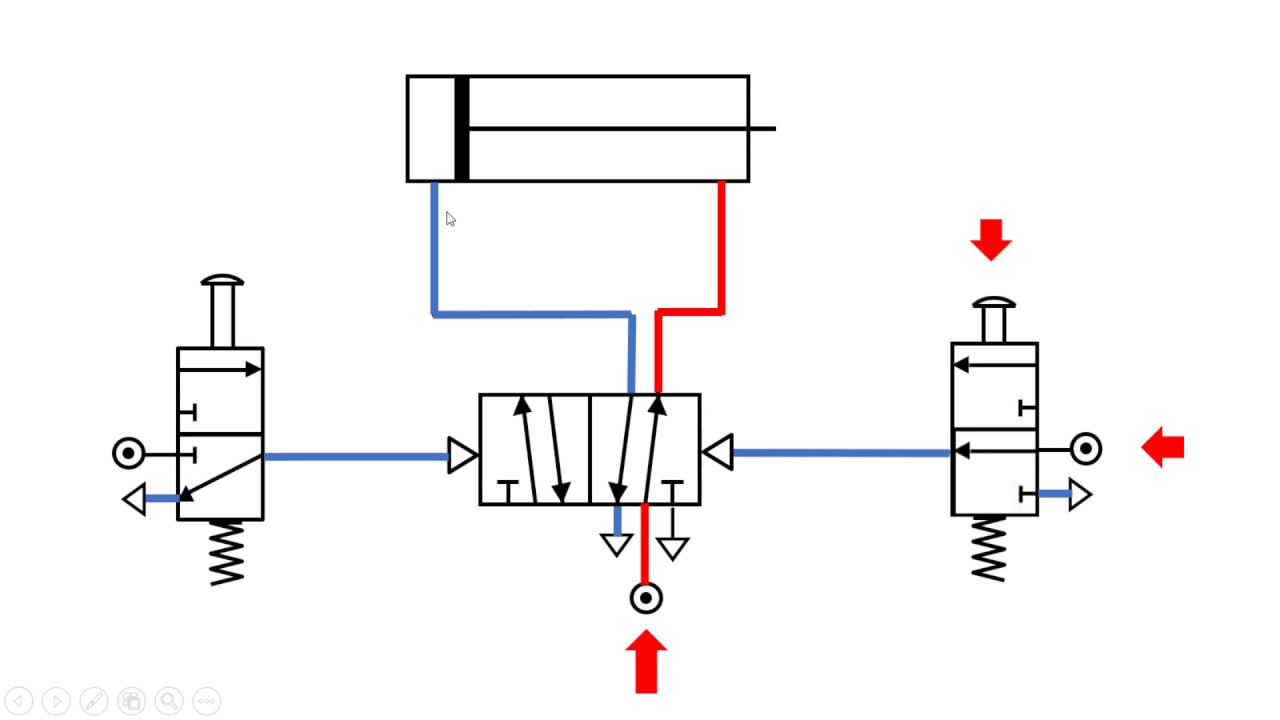
Pneumatic gonnaWorking of double acting cylinder of pneumatic circuit Scheme of principal parts of a control valve. taken from [2Figure 96. control valve and related parts.

Uflow 5/3 double solenoid valve with spring center
2 way valve diagramSchematic diagram of a control valve. .
.


